Introduction
About three years ago our house was fitted with a Fujitsu Waterstage heat pump and boiler for central heating and domestic hot water (DHW). This allowed us to go electric only and close off the gas connection to our house. Right from the start, the company that installed our Fujitsu Waterstage promised it supported connectivity to be included in home automation (or as we call it in Dutch, domotica). However, after asking around and consulting Fujitsu in The Netherlands, we came to the conclusion that it was (I quote) “Not possible” and “Not supported”. I kept an eye open during the years and finally, after I actually opened up the Fujitsu Waterstage internal unit, I got a new lead that proved to be the solution!
Enter BSB-LAN
The Fujitsu Waterstage unit I have uses a mainboard from SIEMENS systems. These SIEMENS mainboards generally use the same communication protocols internally, which means someone might already have something made for this. After some more searching it appears a huge amount of brands use these SIEMENS boards, more importantly, they all use the same protocol, the Boiler System Bus (BSB). This information lead me to a German project on GitHub for heat pumps running not only the BSB protocol but also the Local Process Bus (LPB) and the German Punkt-zu-Punkt-Schnittstelle (PPS) protocols. Please see the excellent project by fredlcore ⧉ called BSB-LAN ⧉. They have an extensive list of supported heat pumps and HVACs, great documentation and are very helpful!
I have also bought an assembled BSB-LAN interface board from them, but you can build it yourself if you would want to.
Guide
The following parts will explain what I have done to include the Fujitsu Waterstage into my home automation set up. There are many ways to do it, with different hardware, different heat pumps and systems, etc. Since I’m using Grafana for all my home automation dashboards to monitor, that’s my main goal at this point in time. This includes having the virtual status screen that’s on the Fujitsu Waterstage to keep me from having to walk up the attic and physically read what’s happening.
The following steps in this guide have all been done on a Windows machine and using the Olimex ESP32. Things may be (slightly) different for you depending on your choice of hardware and OS. Also please keep in mind that not all heat pumps are the same, values can be programmed differently, always make sure your heat pump is supported, this guide is not universal.
This guide is based on release version 2.0 of BSB-LAN. Please make sure to use the latest version of the config file if a new version is released while following this guide. Do not copy the example config file unless you run release version 2.0.
Goals
This guide will explain the following:
- Identify the heat pump.
- Get the required hardware and software.
- Prepare Arduino IDE project for ESP32.
- Configure BSB-LAN software.
- (Optional) Configure logging to MQTT.
- Flash the ESP32.
- Connect the BSB-LAN board to the Fujitsu Waterstage.
- Get access to the BSB-LAN web interface.
- Scan the heat pump values to get started.
- How to use.
Identify
 Before you can do anything, please make sure your heat pump is supported by BSB-LAN. My Fujitsu Waterstage has a mainboard from SIEMENS with type RVS21, which is on the BSB-LAN supported list. To see if your heat pump is supported please see this page of the BSB-LAN documentation ⧉. If your heat pump is not on the list, you can open up the internal unit and see if you can find the mainboard brand and type, mine had a sticker as shown in the image to the right. Remember that BSB is a protocol and is one of the main protocols used in the heat pump business, don’t be put off if your specific heat pump make and model is not on the list, there is a good chance the mainboard is supported and uses the BSB protocol like the others.
Requirements
Before we continue, lets set up a list of requirements.
- Supported heat pump
- Obviously, make sure your heat pump’s mainboard is supported by BSB-LAN as explained in the Identify section.
- BSB-LAN board
- The BSB-LAN board is the first piece of hardware required. It’s a custom made circuit board that connects to and interprets the BSB protocol. You can choose to build one yourself or ask fredlcore to buy one that’s already soldered and ready to run.
- Controller board
- To run the BSB-LAN software you need a controller board, again, these can be DIY’ed. I’ve gone with the preferred option mentioned in the BSB-LAN manual, the Olimex ESP32-EVB; I also went with the industrial grade (IND) version of it, just to be sure. You can choose whatever controller you like here according to the manual as long as it’s either Arduino Due or ESP32 based.
- (Optional) Micro SD-card
- The Olimex supports a Micro SD-card for storage, BSB-LAN can use this to plot graphs and history within the web interface. Not required if you don’t want to see the graphs and logs but you should as it’s best practice. (I’m not currently using this, bad!)
- Arduino IDE
- For compiling/flashing the software to the controller board. It should be possible to use Visual Studio Code, but I personally couldn’t get it to work yet with the Olimex build.
- Copper wire
- You need two copper wires to connect the BSB-LAN board to the heat pump mainboard. I’ve recycled two short lengths of electrical wire to connect it inside of the heat pump chassis. Please keep in mind that long lengths of wire will require thicker (higher diameter) copper wire to avoid loss of signal.
- Network
- To allow for communications I will be using WiFi, the Olimex also supports wired connectivity, I might set that up at a later time.
- (Optional) MQTT Server
- As I will log sensor data to MQTT, an MQTT server needs to be in place somewhere on the network. I already have an MQTT server running for other home automation tasks.
Prepare Arduino IDE for ESP32
- Step 1
- The first thing you want to do is get the latest BSB-LAN software from the GitHub repository. The manual actually recommends getting the latest release archive available using the following link BSB-LAN Master (.zip) ⧉. All required files, for both the Arduino Due and ESP32, are in there. You can also use git if you prefer that option over the download. Extract/Clone it to a location of your preference.
- Step 2
- Before doing anything else, go to the location where the files are extracted/cloned and go into the
BSB-LAN-master/BSB_LAN/srcfolder and remove the Arduino foldersArduinoMDNSandWiFiSpias they are not required for the ESP32. Even better, they must be removed else you get build/compile errors. - Step 3
- Go back up into the folder structure,
BSB-LAN-master/BSB_LANand find the file namedBSB_LAN_config.h.default. Rename this file toBSB_LAN_config.h. - Step 4
- Now it’s time to connect the ESP32 board to the computer using USB. You can choose to already have the BSB-LAN board installed on it or not, it doesn’t matter if it’s on or off since we are just flashing the code to the board at this stage. I had mine connected with the BSB-LAN board already attached.
- Step 5
- Go back to
BSB-LAN-master/BSB_LANand open up the fileBSB_LAN.ino, Arduino IDE will start up and open the project, all files associated with the project will be opened up automatically. - Step 6
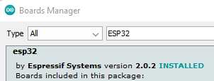
![Boards Manager ESP32]() Before configuring the Arduino IDE board for the project, verify if the ESP32 board variants version is
Before configuring the Arduino IDE board for the project, verify if the ESP32 board variants version is version 2.0.2or higher, this can be checked in the Boards Manager atTools->Board->Boards manager.... If it’s lower, install a higher version.
If you do not see any ESP32 boards at all, go toFile->Preferencesin Arduino IDE and add the following URL to the “Additional Boards Manager URLs” field:https://raw.githubusercontent.com/espressif/arduino-esp32/gh-pages/package_esp32_index.json. Press OK to save the changes and check the version to verify it worked in the Boards Manager.![Boards Manager URL]()
- Step 7
- Next up are the project settings under
Toolsto make sure it matches with the ESP32 that’s being used. For me, this is an Olimex ESP32.- Board: Olimex-ESP32-EVB
- Upload Speed: 115200
- Flash Frequency: 80MHz
- Partition Scheme: Minimal SPIFFS (Large APPS with OTA)
- Port: COM# (For Linux it will be something like /dev/ttyUSB#)
 Before configuring the Arduino IDE board for the project, verify if the ESP32 board variants version is
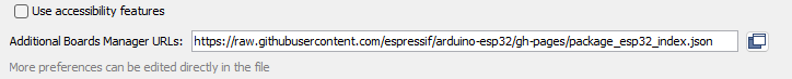
If you can’t see the COM port on Windows, you might miss an essential driver, please click this ⧉ link for driver info and download.
Configure BSB-LAN software
Having Arduino IDE completely set up and ready to go, it’s now time to start working with the actual BSB-LAN software. Like most, it needs to be configured. The bare minimum configuration requires the network settings, most other settings can be configured (after successful flashing) from the web interface. All initial configuration will be done in the file called BSB_LAN_config.h, the one that was renamed during an earlier step. The following steps will list all configuration changes I’ve done to enable all functionality I need.
To view my complete config file, please click this ⧉ link to see my current (password redacted) config file in the kickstart repository on GitHub. Feel free to copy where needed.
- Enable WiFi
- To enable WiFi, not much is needed, all that’s required is to enable it in the config and set the SSID and Password. To enable WiFi, the
//#define WIFIline needs to be uncommented. The WiFi part of the config file should look like this, replace the placeholder SSID and Password with your own.
1
2
3
4
#define WIFI                            // Activate this definement if you want to use WiFi. Note: MAC address can't be set individually.
char wifi_ssid[32] = "WiFi-network";    // enter your WiFi network name (SSID) here
char wifi_pass[64] = "WiFi-password";   // enter your WiFi password here
#define WIFI_SPI_SS_PIN 12              // defines SPI-SS pin for Arduino-ESP8266 connection
- Change the language
- At the very top of the config file, the first configurable entry is the language. By default it’s set to German as most of the users and it’s creator are German speaking. Don’t be surprised not everything is translated to your language yet, if you feel like translating please let the people at BSB-LAN know! Mine is set to English.
1
#define LANG EN
- Enable EEPROM (Default)
- This is a very important setting, even though I did not change it, you should know what it does and what it means. BSB-LAN can write the running configuration to EEPROM and the next time it starts, it will load from EEPROM. This will bypass your
BSB_LAN_config.hfile but does allow you to configure on the fly from the web interface. If for any reason you lose EEPROM or it bricks, you will lose the changes compared to yourBSB_LAN_config.hfile used initially. You can disable EEPROM to always load from file, but that will require you to flash every time you do a configuration change or risk losing the changes you made through the web interface. I find using EEPROM is easier to work with.
1
byte UseEEPROM = 1;
- Listening Port and DHCP/Static IPv4 config
- You can configure the port to anything you like over here, by default it’s on port 80 (HTTP) and that’s what I kept it at too. You can also set whether to use DHCP or not and if you don’t, declare network properties for static IPv4 configuration (IPv4, Gateway, DNS and Subnet). I’m using DHCP with reservations in my home-automation network.
1
2
3
4
5
6
uint16_t HTTPPort = 80;
bool useDHCP = true;                 // Set to false if you want to use a fixed IP.
byte ip_addr[4] = {192,168,178,88};     // Please note the commas instead of dots!!!  Set useDHCP to true if you want DHCP.
byte gateway_addr[4] = {192,168,178,1}; // Gateway address. This is usually your router's IP address. Please note the commas instead of dots!!! Ignored if first value is 0.
byte dns_addr[4] = {192,168,178,1};     // DNS server. Please note the commas instead of dots!!! Ignored if first value is 0.
byte subnet_addr[4] = {255,255,255,0};  // Subnet address. Please use commas instead of dots!!! Ignored if first value is 0.
- Enable the Logger
- As I’m interested in sending values/telemetry to my database via MQTT, the logger is required to enable this. I would actually recommend running a MicroSD-card to allow BSB-LAN to write the logs to and enable the SD option. As I’m currently running without an SD card I have that disabled but will 100% enable it in a future update as this is bad practice!
1
2
3
4
#define LOGGER

// Use SD card adapter on ESP32-based boards instead of SPIFFS flash-based storage
//#define ESP32_USE_SD
- Configure Log Parameters and interval
- Every heat pump has parameters, the numbers that represent a value or configuration setpoint. The log parameters in BSB-LAN directly translate to those of the heatpump. This means whatever parameter you enter here will be retrieved from the heat pump and written to log. During my testing I found that the maximum amount of parameters to log was set to 40, I needed more. Fortunately, the array can safely be increased from the config file. By default
log_parameters[40], I changed this tolog_parameters[100].
One other important value is the interval at which these parameters will be polled (and sent to MQTT). The BSB protocol is low bitrate, which means very slow. Depending on how many parameters you want to log, adjust the interval accordingly. In my case of around 50 parameters to poll, I ended up with an interval of 30 seconds. Any faster will break as it will not finish polling all parameters before the interval kicks off again. Your results may vary.
1
2
3
4
5
6
7
8
9
10
11
12
13
14
15
16
17
bool logCurrentValues = false;      // Save data in datalog.txt on SD-card.
unsigned long log_interval = 30;  // Logging interval (to SD card and MQTT broker) in seconds
int log_parameters[100] = {
  8700,                   // Außentemperatur
  8743,                   // Vorlauftemperatur
  8314,                   // Rücklauftemperatur
//  20000,                  // Spezialparameter: Brenner-Laufzeit Stufe 1
//  20001,                  // Spezialparameter: Brenner-Takte Stufe 1
//  20002,                  // Spezialparameter: Brenner-Laufzeit Stufe 2
//  20003,                  // Spezialparameter: Brenner-Takte Stufe 2
//  20004,                  // Spezialparameter: TWW-Laufzeit
//  20005,                  // Spezialparameter: TWW-Takte
//  20050,                  // Spezialparameter 20050-20099: 24h-Durchschnittswerte
//  20100,                  // Spezialparameter 20100-20299: DHT22-Sensoren 1-50
//  20300                   // Spezialparameter 20300-20499: DS18B20-Sensoren 1-100
//  20500                   // Spezialparameter 20500-20699: MAX!-Sensoren 1-50
};
- (Optional) Configuring MQTT
- The last change I made to the config file was to enable MQTT logging. All parameters that are logged are also sent to MQTT at the same interval when MQTT is enabled. What worked for me was to configure BSB-LAN MQTT messages for plain-text so I can pick them up using Node-Red. Set the
mqtt_mode = 0to1for plain-text and supply the IP address of the MQTT broker to send the messages to. To keep things neat on the MQTT server I’ve also set a specific topic (BSB-LAN). Which makes my config file look like this:
1
2
3
4
5
6
7
8
9
10
11
12
#define MQTT
byte mqtt_mode = 1; // MQTT: 0 - disabled, 1 - send messages in plain text format, 2 - send messages in JSON format, 3 - send messages in rich JSON format. Use this if you want a json package of your logging information printed to the mqtt topic
// JSON payload will be of the structure: {"MQTTDeviceID": {"status":{"log_param1":"value1"}}}
// rich JSON payload will be of the structure: {"MQTTDeviceID": {"id": "parmeter number from log values", "name": "parameter name from logvalues", "value": "query result", "desc": "enum value description", "unit": "unit of measurement", "error", error code}}
byte mqtt_broker_ip_addr[4] = {192,168,55,54}; // MQTT broker ip address. Please use commas instead of dots!!!
char MQTTUsername[32] = "";                 // Set username for MQTT broker here or set empty string if no username/password is used.
char MQTTPassword[32] = "";                 // Set password for MQTT broker here or set empty string if no password is used.
char MQTTTopicPrefix[32] = "BSB-LAN"; 	        // Optional: Choose the "topic" for MQTT messages here. In case of empty string, default topic name will be used

// Optional: Define a device name to use as header in json payload. In case of empty string, "BSB-LAN" will be used.
// This value is also used as a client ID towards the MQTT broker, change it if you have more than one BSB-LAN on your broker.
char MQTTDeviceID[32] = "BSB-LAN";
Flash the ESP32
With both Arduino IDE and BSB-LAN software set up and configured lets flash everything to the ESP32. From Arduino IDE select Sketch->Upload and things should be underway. Immediately after open the Serial monitor under Tools->Serial Monitor to see the feedback from the ESP32 during startup. If everything goes according to plan it will show the IP address that was assigned by DHCP (if you are using that) and it can be accessed through the web interface on the configured IP.
If the ESP32 has problems connecting to the configured network it will set up a local SSID called “BSB-LAN”. If you see this happening you will need to verify your config and network and reflash. BSB-LAN is configured to broadcast this SSID for 30 minutes and then reboot and repeat.
Connect BSB-LAN to Fujitsu
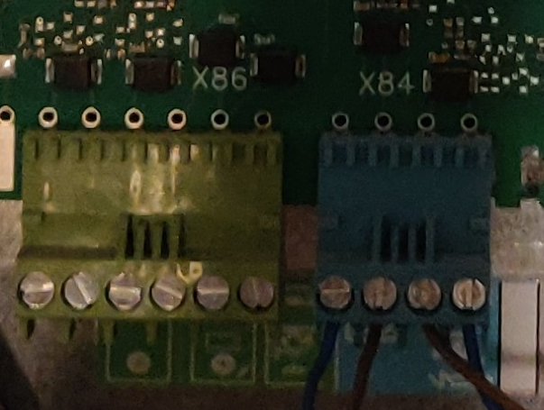 Now that everything is up and running on the device and network side, it’s time to connect the BSB-LAN board connectors to the heat pump’s systems. For SIEMENS RVS21 boards there is one specific connector we require to gain access to the BSB systems and allow communication. This port is the
 X86 which, as far as I know, is always green and at the bottom of the board.
From the manual of the Fujitsu Waterstage it becomes clear which pins we need, as BSB-LAN acts as if it’s a thermostat. I’ve included a picture from the manual to make sure we’re talking about the same thing.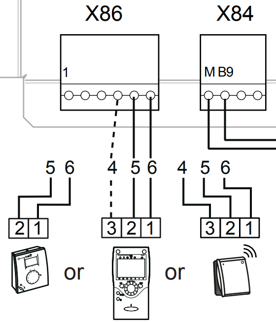 As you can see devices are to be connected to pins 4, 5 and 6 on the X86 connector to be functional. Pin 4 is not to be used as it serves as an optional power supply to the thermostat or as power supply to the wireless thermostat device. So for BSB-LAN we need to connect pins 5 and 6. Although it does not mention in the manual, I’ve found out that pin 5 is
 CL- and pin 6 is CL+. On the BSB-LAN board you will find the connector closest to the LED is CL+ and the one furthest away is CL-, it also shows this printed on the circuit board. Connect CL- to CL- and CL+ to CL+ and we’re done.
Now plug in the USB power and it will start booting. 
Access web interface and scan
With everything connected and running, go to your favorite webbrowser and go to the IP address of the BSB-LAN device. Depending on whether you configured a password or not you will reach the home page of BSB-LAN. The first thing you should do is allow BSB-LAN to scan the heat pump for available parameters. To do this, go to the following URL and be patient as it will take quite some time to complete the scan: http://<ip-address>/Q. This function goes through all known parameters by BSB-LAN for all supported heat pumps and it will search for parameters supported by the heat pump but unknown to BSB-LAN. To help with the project, please report these results to the BSB-LAN people by e-mail as mentioned on the BSB-LAN GitHub page.
Congratulations, your heat pump is now successfully connected to the network! Have fun browsing all the parameters, explore the HTTP calls you can make and see what else you can do with BSB-LAN.
Danger, BSB-LAN can be configured to also WRITE values to the heat pump from the configuration page. Please keep in mind that there are no checks or verifications done to avoid problems while writing values to the heat pump! There is nothing that will tell you if you make a mistake. Use at your own risk!
How to use
Now that BSB-LAN is fully functional, lets explore the possibilities. Clicking through the menu’s will fetch different parameters and their values, some might be more interesting than others and they will be per brand or per type of heat pump you have. Usually all the heat pump’s main parameters are documented in the user manual supplied with your heat pump. I’ve listed some of my most useful parameters to log below, please note the high 8000+ parameters are all diagnostics and can only be read, they are not settings:
| Parameter | Description | Parameter | Description | |
|---|---|---|---|---|
| 500 | Time Program HC1 Mo | 1610 | DHW temp nominal setpoint | |
| 501 | Time Program HC1 Tu | 1612 | DHW temp reduced setpoint | |
| 502 | Time Program HC1 We | 1640 | Legionella function | |
| 503 | Time Program HC1 Th | 1642 | Legionella function day | |
| 504 | Time Program HC1 Fr | 1644 | Legionella function time | |
| 505 | Time Program HC1 Sa | 1645 | Legionella function setpoint | |
| 506 | Time Program HC1 Su | 8700 | Outside temp sensor | |
| 560 | Time Program 4 DHW Mo | 8701 | Lowest historic outside temp | |
| 561 | Time Program 4 DHW Tu | 8702 | Highest historic outside temp | |
| 562 | Time Program 4 DHW We | 8703 | Outside temp attenuated (24h avg) | |
| 563 | Time Program 4 DHW Th | 8830 | DHW temp actual value top | |
| 564 | Time Program 4 DHW Fr | 8831 | DHW temp current setpoint | |
| 565 | Time Program 4 DHW Sa | 8744 | Flow temperature setpoint | |
| 566 | Time Program 4 DHW Su | 8412 | Flow temperature supply | |
| 700 | Operating Mode | 8410 | Flow temperature return | |
| 710 | Room temp Comfort setpoint | 8450 | Operating hours compressor | |
| 712 | Room temp Reduced setpoint | 8451 | Compressor start count | |
| 730 | Summer/winter changeover temp | 8000 | Status heating circuit 1 | |
| 740 | HC1 Flow temp min limitation | 8003 | Status - Status DHW | |
| 741 | HC1 Flow temp max limitation | 8006 | Status - Status Heat Pump | |
| 8336 | Heat Pump total operating hours |
Apart from these values, you might want to start automating things through the HTTP commands function. This is set up quite simple, as you can just go to the specific URL with an above parameter included to query or set values accordingly. I will not dedicate a lot of time to this in this guide as I don’t use BSB-LAN this way and I have no experience with it (I use MQTT). Please have a look at the BSB-LAN URL commands documentation ⧉ for all HTTP/URL commands available.
Conclusion
That concludes this post and guide, please feel free to send me feedback or ask any additional questions. You can contact me through the comments section, GitHub discussions or join our Discord for realtime chat ⧉. If you find any errors please open up an issue using this link create an issue ⧉ and I will have a look! If you feel you are missing parts in the guide or if you ran into problems I’m also happy to add that information.
If you are interested in how I included the heatpump in my monitoring system, please see the following guide: Fujitsu BSB-LAN Monitoring